Handbook for selection of motors
Technical details for your Product
-
Attention! Following information only applies for the blowers of the series
BB, BU, TB, and TU.
Flow rate definition
The flow rate in volume is the fluid volume passing through the fan in the time unit.
Knowing the flow rate of a blower, connected to a duct, the speed of the fluid can be calculated by the formula:
v = Qv / (A x 3.600)
Where to find:
v = Average fluid speed in m/s
Qv = Flow rate in m3/h
A = Area of the duct section in m2
Vice versa, knowing the speed v of the fluid and the section area A of the duct, the flow rate can be calculated:
Qv = v • A • 3600
Where to find:
Qv = Flow rate in m3/h
v = Average speed of the fluid in m/s
A = Area of the duct section in m2
Total, static and velocity pressure definition
When moving fluid three types of pressure can be distinguished.
1 - Static pressure (Ps)
This is defined as the pressure of the fluid exercised on the walls of the duct or the recipient where it is contained.
This acts in all directions and is independent of fluid speed. Taking ambient pressure as reference, the static pressure is positive when it is greater than ambient pressure,
and negative when it is lower.
2 - Velocity pressure (Pd)
This is defined as the pressure corresponding to the energy part contained in the fluid mass unit because of its speed (kinetic energy).
This acts in the same direction as the fluid moves and is always considered positive.
The velocity pressure is function of the fluid density and speed and is expressed by the following formula:
Pd = ½ x ρ x v2
Where to find:
Pd = Velocity pressure in Pa (Pascal)
ρ = Fluid density in Kg/m3
v = Fluid velocity in m/s
3 - Total pressure (Pt)
Pt = Ps + Pd
Special working conditions of the blower are:
a) Closed inlet and / or outlet (sealed condition)
b) Inlet and outlet not attached to ducts (free-flow condition)
Working at sealed condition, the flow rate is zero. Therefore, the fluid speed and the velocity pressure are zero. In the case: Pt = Ps
Working at free-flow condition, the static pressure is zero and the pressure generated by the blower is all kinetic. In this case: Pt = Pd
Blower performance curve
The performance describes a blower’s ability to deliver flow through resistance from zero backpressure (“free flow”) to complete blocked flow (“sealed”)
System resistance curve
The resistance to flow given by the system, ductwork, filters and other obstructions creates a loss of static pressure in the flow system, often referred to as backpressure or head loss, and each blower has a characteristic curve that describes the maximum amount of resistance that it can overcome to provide a given flow rate.
The system curve can be estimated according to the relationship:
P = K x Q2
where:
P = Pressure drop
K = Coefficient depending on the characteristic of the system (fluid movement resistance)
Q = Flow rate
If the desired operating point is known, then its associated system curve can be estimated according to the relationship P = K x Q2. Plugging the values for desired operating point into the P (pressure drop) and Q (flow rate) terms yields the constant K.
The blower performance curves are usually plotted as static pressure (or vacuum) vs flow rate. The velocity pressure is typically not a useful energy quantity for overcoming resistance to flow. In other words, in most cases the resistance to flow results in a loss of static pressure of the streamline and not a loss of velocity pressure.
Operating point
The intersection of the blower performance curve and the system resistance curve is the actual operating point. The static pressure rise provided by the blower matches the static pressure loss imposed by the system resistance.
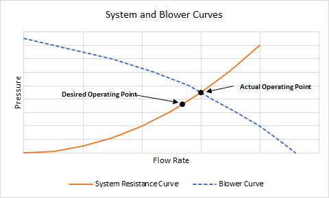
A diagram of a system and blower curves
-
Attention! Following information only apply to the motors of the series BL, DU and PM.
For many applications, it is sufficiently accurate to take the most important data from the motor characteristic diagrams and data tables. Although tolerances and temperature influences are not taken into account, the data is accurate enough for approximate calculations. The degree of protection quoted relates only to the housing – adequate sealing of the shaft is the responsibility of the customer.
The values in the data tables are according to EN60034 and base on a „detached“ motor, which means mounted thermally insulated to a flange. Under real operating conditions, the nominal torque of the motor is much higher in most cases because a direct connection to the flange results in better heat dissipation.
Nominal voltage UN (VAC/DC)
The voltage that is applied to the commutation electronics as a system supply voltage. All rated data in our catalogues are with reference to this voltage. Motor applications are, however, not restricted to this voltage.
Rated current IN (A)
The current drawn from a source when the motor is operating at rated torque.
Rated torque MN (Ncm)
The torque that can be produced by the motor, operating continuously, in an ambient temperature of 20°C. (2)
Rated speed nN (min-1)
The speed of the motor when it is operating at rated torque.
Maximum Speed nN (min-1)
The maximum allowed operation speed of the blower/motor
Holding torque MA (Ncm)
Maximum Torque that is generated at speed 0.
In some cases this is a theoretical value, e.g. if the integrated electronics limits the torque or if the motor is demagnetised at lower currents. Then, the maximum possible Value is specified. (4a)
No-load speed (rpm)
Speed that is reached if the corresponding nominal voltage is applied to the motor without mechanical load. (5)
Rated power PN (W)
The output power which the motor can produce continuously; it is calculated from rated speed and rated torque.
Maximum output power Pmax (W)
Maximum mechanical output power the motor can generate at nominal voltage. This power can only be generated for a limited period.
Torque constant Ra (N/A)
Represents the correlation between input current and output torque.
Connecting resistance Ra (Ω)
Typical ohmic connecting resistance phase to phase (BG motors) or between (+) and (-) (G / GR motors).
Connecting inductance La (mH)
Typical connecting inductance phase to phase (Brushless motors) or between (+) and (-) (AC / DC motors).
Peak current Imax (A)
The maximum current for motors with integral electronics or solo motors.
Starting current Imax (A)
The current required to produce the starting torque. For motors with electronics, the starting current may be higher than the permissible peak current.
Rotor moment of inertia JR (gcm2)
The moment of inertia of the rotor is the factor that determines the dynamic properties of a motor.
-
Attention! Following information only apply to the motors of the series ST.
Pull out torque [Ncm]
Characteristic curve for stepper motor consists of pull out torque. Means maximum torque that can be applied to a motor when already in movement. Pull out torque is not directly usable for acceleration.
Step Los
If the pull-out torque is exceeded, the synchronization between rotor and magnetic field can be lost. This results in step losses. The use of encoders can prevent this.
Rated phase current [A]
The DC current that the motor can be continuously supplied with. Same motor size usually comes available with different current ratings. All of them have the same holding torque. Difference in dynamic behavior. Lower current rating reach same holding torque with same current, but performance drops at higher speed. For higher speed more nominal current is better.
Maximum current [A]
Maximum current that motor can withstand for some seconds. More current allows for more torque generation. Allows to overload the motor. Is not possible for 100% duty cycle. Fore a certain time the motor can generate more than 100% torque.
Holding torque [Ncm]
Holding torque is maximum torque that can be applied to the shaft of an energized motor with DC nominal current without causing a continuous rotation. Does not give information about motor behavior during rotation. Always higher than maximum pull-out torque.
Maximum voltage [VDC]
Maximum voltage that can be applied on motor phase. Actual voltage determines dynamic performances. Lower voltages result in early pull out torque drop when increasing the velocity. Higher voltages shift this value later on the velocity axis.
-
The specified torques of the gearboxes with metal housing base on a typical lifetime of 3,000 h of effective operation at 3,000 rpm input speed and the corresponding specified operating mode. In practice, this value may deviate considerably up or down, depending on temperature, acceleration torque and -time and impact forces from outside, etc.
When sizing a motor gearbox combination, we have to make sure that the specified gearbox torque is not exceeded. This is important for the nominal torque and also for the acceleration torque. If a peek torque occurs, the emergency stop torque ME-Stop must not be acceded.
Applicable is:
MN-Mo x i x ηGe ≤ MN-Ge
Based on the calculations it might be necessary to reduce the motor torque by limiting the motor current to bring it into the specified range. Another option is to add a coupling to the output-shaft of the gearbox and therefore make sure the gearbox is not overloaded.
MAcc-Mo x i x ηGe ≤ MAcc-Ge
MN-Mo = Nominal Torque of Motor
i = Ratio of Gearbox
ηGe = Efficiency of Gearbox
MN-Ge = Nominal Torque of Gearbox
MAcc-Mo = Acceleration Torque of Motor
MAcc-Ge = Acceleration Torque of Gearbox
Drive dimensioning
In the wide range of MAE and Dunkermotoren products, you will find a suitable drive for almost any requirement in the power range of 1 – 5,000 Watt.
The following points should be taken into account when selecting motors and gearboxes:
» Which operating mode is used (continuous operation = S1 or periodic operation = S5)?
» What is the expected working life of the motor?
» Which torque and which speed are required?
» How much space is available for the motor?
» What is the available supply voltage? DC or AC?
» Are there special environmental conditions (temperature, humidity, vibration, ...)?
» To what degree can heat be conducted away from the motor?
» Are there exceptional axial and radial shaft loads to be considered?
» What are the requirements for the motor control electronics?
» Is the motor to be controlled online via a bus system?
» Do you need a brake or an encoder?
For dimensioning a suitable motor, determining the required torque plays a decisive role to avoid thermal overload of the motor. For combining a drive system consisting of motor and control electronics, it is important to ensure that permissible values for the motor are not exceeded by the electronics. Depending on the required output speed, either a motor or a motor-gearbox combination may be selected. The choice of a reduction gearbox will largely depend on the recommended maximum torque in continuous operation. For intermittent duty, loading above the rated torque is possible.
We will be pleased to carry out a precise adaptation of a motor to your operating conditions.